Specifications
Please contact Esteves Group sales to select the best suitable stone size for your specific requirement.
| Blank Type (1) | Self-supported (without support ring) | Thermally stable self-supported (without support ring) | ||||||
|---|---|---|---|---|---|---|---|---|
| ADDMA size | D6 | D12 | D15 | D18 | D6 | D12 | D15 | D18 |
| S – Maximum recommended die hole diameter when drawing soft wire – inches [millimeters] | ||||||||
| max. new diameter (2) | .0197 [0.5] | .0394 [1.0] | .0591 [1.5] | .0787 [2.0] | .0197 [0.5] | .0394 [1.0] | .0591 [1.5] | .0787 [2.0] |
| max. recut diameter (3) | .0394 [1.0] | .0551 [1.4] | .0866 [2.2] | .1102 [2.8] | .0394 [1.0] | .0551 [1.4] | .0866 [2.2] | .1102 [2.8] |
| H – Maximum recommended die hole diameter when drawing hard wire – inches [millimeters] | ||||||||
| max. new diameter (2) | .0138 [0.4] | .0276 [0.7] | .0413 [1.1] | .0551 [1.4] | .0138 [0.4] | .0276 [0.7] | .0413 [1.1] | .0551 [1.4] |
| max. recut diameter (3) | .0276 [0.7] | .0386 [1.0] | .0606 [1.5] | .0772 [2.0] | .0276 [0.7] | .0386 [1.0] | .0606 [1.5] | .0772 [2.0] |
| Grain Size (μm) | ||||||||
| 1 | D6-N1 | D12-N1 | D15-N1 | D18-N1 | D6-T1 | D12-T1 | D15-T1 | D18-T1 |
| 3 | – | – | – | – | – | – | – | – |
| 5 | D6-N5 | D12-N5 | D15-N5 | D18-N5 | D6-T5 | D12-T5 | D15-T5 | D18-T5 |
| 12 | D6-N12 | D12-N12 | D15-N12 | D18-N12 | D6-T12 | D12-T12 | D15-T12 | D18-T12 |
| 25 | D6-N25 | D12-N25 | D15-N25 | D18-N25 | D6-T25 | D12-T25 | D15-T25 | D18-T25 |
| 50 | – | – | – | – | – | – | – | – |
| Standard casing dimensions (4) | ||||||||
| diameter x height [inch] | 1 1/8 x 3/8 | 1 1/8 x 3/8 | 1 1/8 x 1/2 | 1 1/8 x 1/2 | 1 1/8 x 3/8 | 1 1/8 x 3/8 | 1 1/8 x 1/2 | 1 1/8 x 1/2 |
| diameter x height [mm] | 28 x 8 | 28 x 10 | 28 x 12 | 28 x 15 | 28 x 8 | 28 x 10 | 28 x 12 | 28 x 15 |
| Blank Type (1) | Supported (with tungsten carbide support ring) | |||||||
|---|---|---|---|---|---|---|---|---|
| ADDMA size | D12 | D15 | D18 | D21 | D24 | D24 | D27 | D27 |
| S – Maximum recommended die hole diameter when drawing soft wire – inches [millimeters] | ||||||||
| max. new diameter (2) | .0315 [0.8] | .0709 [1.8] | .0906 [2.3] | .1378 [3.5] | .1811 [4.6] | .2047 [5.2] | .2126 [5.4] | .2283 [5.8] |
| max. recut diameter (3) | .0394 [1.0] | .0866 [2.2] | .0945 [2.4] | .1457 [3.7] | .1969 [5.0] | .2362 [6.0] | .2362 [6.0] | .2953 [7.5] |
| H – Maximum recommended die hole diameter when drawing hard wire – inches [millimeters] | ||||||||
| max. new diameter (2) | .0220 [0.6] | .0496 [1.3] | .0634 [1.6] | .0965 [2.5] | .1268 [3.2] | .1433 [3.6] | .1488 [3.8] | .1598 [4.1] |
| max. recut diameter (3) | .0276 [0.7] | .0606 [1.5] | .0661 [1.7] | .1020 [2.6] | .1378 [3.5] | .1654 [4.2] | .1654 [4.2] | .2067 [5.3] |
| Grain Size (μm) | ||||||||
| 1 | D12-S1 | D15-S1 | D18-S1 | – | – | – | – | – |
| 3 | D12-S3 | D15-S3 | D18-S3 | D21-S3 | D24-S3 | – | – | – |
| 5 | D12-S5 | D15-S5 | D18-S5 | D21-S5 | D24-S5 | – | D27d-S5 | D27-S5 |
| 12 | D12-S12 | D15-S12 | D18-S12 | D21-S12 | D24-S12 | – | D27d-S12 | D27-S12 |
| 25 | D12-S25 | D15-S25 | D18-S25 | D21-S25 | D24-S25 | D24c-S25 | D27d-S25 | D27-S25 |
| 50 | – | D15-S50 | D18-S50 | D21-S50 | D24-S50 | D24c-S50 | – | D27-S50 |
| Standard casing dimensions (4) | ||||||||
| diameter x height [inch] | 1 1/8 x 3/8 | 1 1/8 x 1/2 | 1 1/8 x 1/2 | 1 1/8 x 5/8 | 1 1/8 x 5/8 | 1 1/8 x 5/8 | 1 1/2 x 7/8 | 1 1/2 x 7/8 |
| diameter x height [mm] | 28 x 10 | 28 x 12 | 28 x 15 | 28 x 15 | 28 x 15 | 28 x 15 | 43 x 27 | 43 x 27 |
| Blank Type (1) | Supported (with tungsten carbide support ring) | ||||||||
|---|---|---|---|---|---|---|---|---|---|
| ADDMA size | D30 | D33 | D36 | D39 | |||||
| S – Maximum recommended die hole diameter when drawing soft wire – inches [millimeters] | |||||||||
| max. new diameter (2) | .2992 [7.6] | .4409 [11.2] | .4724 [12.0] | .4921 [12.5] | .5000 [12.7] | .6181 [15.7] | .7480 [19.0] | 1.0118 [25.7] | 1.1417 [29.0] |
| max. recut diameter (3) | 8.0 | 12.2 | 13.0 | 13.5 | 13.5 | 19.0 | 21.0 | 30.0 | 35.0 |
| H – Maximum recommended die hole diameter when drawing hard wire – inches [millimeters] | |||||||||
| max. new diameter (2) | .2094 [5.3] | .3087 [7.8] | .3307 [8.4] | .3445 [8.8] | .3500 [8.8] | .4327 [11.0] | .5236 [13.3] | .7083 [18.0] | .7992 [20.3] |
| max. recut diameter (3) | .2205 [5.6] | .3362 [8.5] | .3583 [9.1] | .3720 [9.5] | .3720 [9.5] | .5236 [13.3] | .5787 [14.7] | .8268 [21.0] | .9646 [24.5] |
| Grain Size (μm) | |||||||||
| 1 | – | – | – | – | – | – | – | – | – |
| 3 | – | – | – | – | – | – | – | – | – |
| 5 | D30-S5 | – | – | – | – | – | – | – | – |
| 12 | D30-S12 | – | – | – | – | – | – | – | – |
| 25 | D30-S25 | D30c-S25 | D33b-S25 | D33c-S25 | D36-S25 | D36c-S25 | D36d-S25 | D39-S25 | D39b-S25 |
| 50 | D30-S50 | – | – | – | – | – | – | – | – |
| Standard casing dimensions (4) | |||||||||
| diameter x height [inch] | 1 1/2 x 7/8 | 1 1/2 x 7/8 | 1 1/2 x 7/8 | 1 1/2 x 7/8 | 2 x 1 1/8 | 2 x 1 1/8 | 2 x 1 1/8 | 3 x 1 3/16 | 3 x 1 3/16 |
| diameter x height [mm] | 42 x 27 | 42 x 27 | 75 x 40 | 75 x 40 | made to order | made to order | made to order | made to order | made to order |
- Operating temperature for thermally stable blanks should not exceed 1562°F (850°C). Operating temperature should not exceed 1202°F (650°C) for all other blanks.
- Maximum recommended diameters for new dies are advised by die blank supplier
- Maximum recommended diameters for recut dies are calculated for 21% wire elongation with the following geometries:
– soft wire: reduction angle: 18°, bearing length 30%
– hard wire: reduction angle: 12°, bearing length 30% - Other casing dimensions are available on request
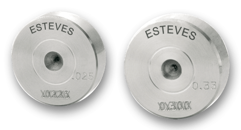
| Standard product coding | Blank material | Engraving |
|---|---|---|
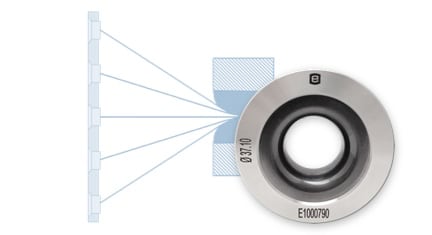
| Polycrystalline Diamond (PCD) |  |
Please contact Esteves Group for any special engraving requirements.
| PCD Wire Drawing Die Standard Tolerances | Imperial tolerances [inch] | Metric tolerances [mm] | ||||
|---|---|---|---|---|---|---|
| Diameter | Tolerance | Max. ovality | Diameter | Tolerance | Max. ovality | |
| .00083 – .00560 | ± .00002 | .00002 | 0.021 – 0.141 | ± 0.00051 | 0.00051 | |
| .00561 – .00891 | ± .00003 | .00003 | 0.142 – 0.226 | ± 0.00076 | 0.00076 | |
| .00892 – .01263 | ± .00004 | .00004 | 0.227 – 0.320 | ± 0.00102 | 0.00102 | |
| .01264 – .02009 | ± .00005 | .00005 | 0.321 – 0.510 | ± 0.00127 | 0.00127 | |
| .02010 – .02845 | ± .00006 | .00006 | 0.511 – 0.722 | ± 0.00152 | 0.00152 | |
| .02846 – .04029 | ± .00007 | .00007 | 0.723 – 1.023 | ± 0.00178 | 0.00178 | |
| .04030 – .05706 | ± .00008 | .00008 | 1.024 – 1.449 | ± 0.00203 | 0.00203 | |
| .05707 – .08079 | ± .00009 | .00009 | 1.450 – 2.051 | ± 0.00229 | 0.00229 | |
| .08080 – .14427 | ± .00010 | .00010 | 2.052 – 3.664 | ± 0.00254 | 0.00254 | |
| .14428 – .22941 | ± .00012 | .00012 | 3.665 – 5.826 | ± 0.00305 | 0.00305 | |
| .22942 – .32485 | ± .00014 | .00014 | 5.827 – 8.250 | ± 0.00356 | 0.00356 | |
| .32486 – .36479 | ± .00016 | .00016 | 8.251 – 9.265 | ± 0.00406 | 0.00406 | |
| .36480 – .40963 | ± .00018 | .00018 | 9.266 – 10.404 | ± 0.00457 | 0.00457 | |
| .40964 – .45999 | ± .00020 | .00020 | 10.405 – 11.683 | ± 0.00508 | 0.00508 | |
| .46000 – .51654 | ± .00022 | .00022 | 11.684 – 13.119 | ± 0.00559 | 0.00559 | |
| .51655 – .58004 | ± .00024 | .00024 | 13.120 – 14.732 | ± 0.00610 | 0.00610 | |
| .58005 – .65135 | ± .00026 | .00026 | 14.733 – 16.544 | ± 0.00660 | 0.00660 | |
| .65136 – .73142 | ± .00028 | .00028 | 16.545 – 18.577 | ± 0.00711 | 0.00711 | |
| .73143 – .82134 | ± .00030 | .00030 | 18.578 – 20.861 | ± 0.00762 | 0.00762 | |
| .82135 – .92232 | ± .00032 | .00032 | 20.862 – 23.426 | ± 0.00813 | 0.00813 | |
| .92233 – 1.3780 | ± .00035 | .00035 | 23.427 – 35.000 | ± 0.00889 | 0.00889 | |
Tighter tolerances are available when required.
Call now to see how our PCD dies can help improve the quality of your wire.
1-800-325-7989